Introduction to Manual Transmission Systems
Understanding the components of a manual transmission system – Manual transmissions, commonly referred to as stick shifts, are a fundamental part of automotive history. These systems offer drivers direct control over the powertrain, allowing for precise gear selection and optimized performance. Historically, manual transmissions were ubiquitous in vehicles, but their prevalence has decreased with the rise of automatic transmissions. However, their unique characteristics still appeal to many enthusiasts and are valued for their control and fuel efficiency in some applications.Manual transmissions are sophisticated mechanical systems that link the engine’s power to the drive wheels.
By changing gears, the driver adjusts the engine’s output to match the vehicle’s speed and load. This allows for optimal performance in various driving conditions, from accelerating on a highway to climbing a steep hill. The precise control offered by a manual transmission is a key factor in its enduring appeal.
Core Components of a Manual Transmission
Manual transmissions are composed of several interconnected components, each playing a crucial role in the power transmission process. Understanding these components and their functions is essential to appreciating the intricate mechanics of this system.
| Component Name | Description | Function | Image Description |
|---|---|---|---|
| Gearbox (Transmission Case) | The housing that contains all the internal components of the transmission. | Provides a rigid structure to support and house the gears, shafts, and other internal components. | Imagine a sturdy metal box, roughly the size of a large book, with various openings and ports for input and output shafts. |
| Gears | Interlocking toothed components that transfer power. | Transfer rotational power from the engine to the drive wheels by meshing with other gears at various ratios. Different gear ratios provide different levels of speed and torque. | Visualize multiple toothed wheels of different sizes, interlocked in a precise manner. Some gears are larger and some smaller, reflecting different gear ratios. |
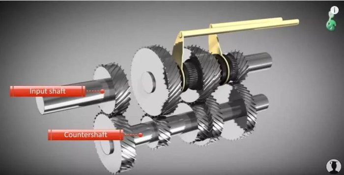
| Input Shaft | The shaft that receives power from the engine. | Transmits the rotational force from the engine’s crankshaft to the transmission. | Picture a solid metal rod extending into the gearbox from the engine’s side. |
| Output Shaft | The shaft that transmits power to the drive wheels. | Carries the rotational power from the transmission to the differential or final drive. | Imagine a solid metal rod extending out of the gearbox to the rear axle or front axle. |
| Clutch | A mechanical component that disconnects the engine from the transmission. | Allows the driver to engage or disengage the engine’s power to the transmission. This is essential for shifting gears and avoiding damage to the transmission and engine. | Visualize a plate or a set of plates that can be pressed together to engage or disengage power. A pressure plate is typically part of this component. |
| Shift Fork | A lever or set of levers that actuate the gear selection mechanism. | Moves the gears into the desired position within the transmission. | Visualize a series of levers or arms that are connected to the gears and operate based on the driver’s shifting input. |
| Shift Linkage | The mechanical linkage that connects the gear shift lever to the shift fork. | Transmits the driver’s input from the gear shift lever to the shift fork, allowing the driver to change gears. | Imagine a series of rods or cables that are interconnected. The driver’s input through the gear lever will operate these mechanical components, ultimately affecting the gear position. |
Gears and Gear Ratios
Gears are fundamental components in a manual transmission system, enabling the engine’s rotational speed to be adjusted to match the vehicle’s speed and load. Different gear ratios allow the transmission to optimize power delivery for various driving conditions. Understanding these ratios is crucial for efficient and controlled vehicle operation.Gear ratios are essentially the relationship between the rotational speeds of the input and output shafts of a gear set.
A higher gear ratio means the output shaft rotates slower than the input shaft, and vice versa. This relationship is critical in adapting the engine’s power to the vehicle’s needs.
Gear Ratio Definitions
Gear ratios are expressed as a numerical value, typically a fraction. For example, a gear ratio of 3:1 means the output shaft rotates three times for every one rotation of the input shaft. A higher numerical ratio signifies a lower gear.
Purpose of Different Gear Ratios
Different gear ratios are designed to optimize performance in different driving conditions. Lower gears provide greater torque, ideal for accelerating from a standstill or climbing steep hills. Higher gears provide higher speeds but with reduced torque, suitable for cruising at steady speeds on flat roads.
Examples of Gear Ratios
Typical gear ratios for different gears in a manual transmission system vary significantly. Here are examples for illustrative purposes:
- 1st gear: A gear ratio of 2.90:1 is common in many vehicles. This provides maximum torque for starting and accelerating from a standstill.
- 2nd gear: A ratio of 1.80:1 allows for increased speed while maintaining substantial torque, enabling efficient acceleration after 1st gear.
- 3rd gear: A ratio of 1.30:1 provides a balance between speed and torque, suited for moderate acceleration and highway driving.
- 4th gear: A ratio of 0.90:1 or 0.80:1 is common in many vehicles, offering a higher speed for highway cruising with reduced torque.
- 5th gear: A gear ratio of 0.70:1 or lower is typically the highest gear, maximizing speed while maintaining efficiency at lower engine RPMs. This is ideal for high-speed cruising.
Gear Ratio Comparison Table
The table below summarizes the relationship between gear ratios and the corresponding vehicle speeds, assuming a constant engine speed. Note that actual speeds will vary based on factors such as road conditions, incline, and vehicle weight.
| Gear | Gear Ratio | Estimated Speed (at constant engine speed) |
|---|---|---|
| 1st | 2.90:1 | Low |
| 2nd | 1.80:1 | Intermediate |
| 3rd | 1.30:1 | Moderate |
| 4th | 0.90:1 | High |
| 5th | 0.70:1 | Very High |
Clutches

Source: transpartswarehouse.com
The clutch is a crucial component in a manual transmission system, acting as a mechanical interface between the engine and the transmission. Its primary function is to allow the driver to smoothly engage and disengage the power flow from the engine to the transmission, enabling gear changes without the jarring effects of abruptly connecting or disconnecting the power source.The operation of a clutch is fundamental to smooth and controlled gear shifting, preventing harsh jolts or engine stalling.
Proper clutch control is essential for safe and efficient vehicle operation.
Types of Clutches
Various clutch types exist, each with unique characteristics influencing performance and durability. Understanding these differences is key to appreciating the nuances of manual transmission operation.
- Single-plate clutches are the most common type in passenger cars. Their simplicity and relatively low cost contribute to their widespread use. These clutches typically feature a single friction plate between the engine flywheel and the transmission input shaft. The friction surface allows for controlled engagement and disengagement of the power train.
- Multi-plate clutches, in contrast, offer greater torque capacity and smoother engagement. They utilize multiple friction plates, allowing for a more gradual and controlled transfer of power, which is particularly advantageous in heavier vehicles or applications requiring higher torque output. This design increases the surface area for friction, enhancing the clutch’s ability to handle greater torque demands.
- Centrifugal clutches are primarily used in applications requiring automatic engagement and disengagement, such as some small engines or light-duty vehicles. Their operation is based on centrifugal force, engaging automatically as the engine speed increases. The clutch design makes them suitable for situations where automatic engagement is preferred, reducing the need for manual intervention.
Clutch Mechanism
The clutch mechanism involves a set of components working in concert to engage and disengage the power train. The fundamental process involves a friction surface that engages when the clutch is depressed, transferring power, and disengages when the clutch is released.
The clutch plate, situated between the engine flywheel and the transmission input shaft, is the core element of the engagement and disengagement process. When the clutch pedal is depressed, the clutch plate is separated from the flywheel, breaking the connection between the engine and the transmission. Conversely, when the clutch pedal is released, the friction surfaces are brought into contact, allowing the power to flow from the engine to the transmission.
Importance of Smooth Clutch Operation
Smooth gear changes are a direct result of proper clutch control. A gradual release of the clutch pedal, matched with precise timing of the gear shift, ensures a seamless transition between gears. Conversely, abrupt clutch engagement or disengagement can cause the vehicle to lurch or stall, jeopardizing safety and efficiency.
Comparison of Clutch Types
| Clutch Type | Advantages | Disadvantages |
|---|---|---|
| Single-plate | Simple design, low cost, reliable operation. | Lower torque capacity compared to multi-plate, may not be suitable for high-performance applications or heavy vehicles. |
| Multi-plate | Higher torque capacity, smoother engagement, suitable for heavy vehicles or high-performance applications. | More complex design, potentially higher cost, more susceptible to wear and tear. |
| Centrifugal | Automatic engagement, simple operation, good for light-duty applications. | Limited adjustability, may not offer the same level of control as a manual clutch. |
Shafts and Couplings
Manual transmission systems rely on a network of shafts and couplings to efficiently transfer power from the engine to the wheels. These components are crucial for smooth gear changes and reliable operation. Understanding their roles and characteristics is essential for comprehending the overall function of the transmission.The input shaft receives rotational power from the engine’s crankshaft, while the output shaft delivers that power to the wheels.
Couplings act as connectors between shafts and other components, ensuring the seamless flow of power. Different types of shafts and couplings are employed to meet specific design requirements and performance goals. Proper alignment is vital for minimizing friction and maximizing efficiency.
Input Shaft Function
The input shaft, typically located near the engine, receives torque from the crankshaft. It’s responsible for transmitting this rotational power to the transmission’s gears. This shaft is often designed with a splined or keyed connection to the flywheel for smooth torque transfer.
Output Shaft Function
The output shaft, situated near the transmission’s output, receives the rotational power from the gears. It’s connected to the driveshaft, which then transmits the power to the wheels. The output shaft often incorporates features like bearings and splines for efficient power delivery.
Coupling Function
Couplings are critical for transmitting power between rotating shafts. They allow for some degree of misalignment, compensating for minor manufacturing tolerances or vibration. This flexibility is vital in dynamic systems like manual transmissions. Couplings also help isolate vibrations, which reduces stress on other components.
Types of Shafts
- Spur Shafts: These shafts feature straight teeth and are common in many gear systems due to their simplicity and robustness. They are typically used where high torque and precise speed ratios are not critical, such as in lower-speed applications.
- Helical Shafts: Helical shafts use helical gear teeth, which offer smoother operation and reduced noise compared to spur shafts. They are frequently found in applications requiring higher speeds and less noise, like higher-performance vehicles.
- Herringbone Shafts: These shafts incorporate two sets of helical gears on opposite sides, effectively canceling out vibrations. They are employed in applications demanding high torque and efficiency, such as heavy-duty transmissions.
The choice of shaft type depends on the specific application, considering factors such as torque requirements, speed, and desired noise levels.
Types of Couplings
- Rigid Couplings: These couplings provide a direct connection between shafts, offering a strong, stable connection. They are often used where precise alignment is achievable, minimizing any potential play.
- Flexible Couplings: Flexible couplings allow for some misalignment between shafts. This adaptability is crucial in applications where shaft alignment may shift due to vibrations or thermal expansion. They are common in vehicles due to the inherent vibration of the engine.
- Jaw Couplings: These couplings utilize a clamping mechanism to connect the shafts. Their simple design and low cost make them suitable for various applications, but their performance is less efficient in high-speed, high-vibration environments.
The selection of a coupling depends on the need for flexibility and the amount of misalignment expected.
Importance of Shaft and Coupling Alignment
Proper alignment of shafts and couplings is paramount for optimal performance. Misalignment leads to increased friction, heat generation, and potential damage to the components. It also reduces efficiency, resulting in a loss of power. A well-aligned system ensures smooth operation and extended component life.
Diagram of Power Flow
A simplified diagram illustrating the power flow is shown below.
(Insert a simplified diagram here, showing the crankshaft, input shaft, gears, output shaft, and driveshaft. Label each component clearly.)
This diagram demonstrates the pathway of power from the engine to the wheels, highlighting the role of each component in the process. The diagram would clearly show the sequence of power transmission, emphasizing the smooth transition between the crankshaft, input shaft, gears, output shaft, and driveshaft to the wheels.
Synchronizers
Synchronizers are crucial components in manual transmissions, enabling smooth and efficient gear changes. They prevent the clashing of gears during shifts, which would result in jarring or damaging the transmission. This is achieved by a carefully designed mechanism that precisely matches the rotational speeds of the input and output shafts before the gear engagement.Synchronizers function as a kind of speed-matching device, ensuring the gears align properly and engage without impact.
They are critical for a comfortable and reliable driving experience. The effectiveness of synchronizers is directly related to the driver’s skill in managing the clutch and the speed of the vehicle during gear changes.
Synchronizer Function
Synchronizers are located within the transmission housing, positioned between the gears and the input shaft. They utilize friction materials to gradually bring the input shaft’s speed into alignment with the output shaft’s speed, which is crucial for engaging the next gear. This controlled speed matching is vital for avoiding harsh gear changes and extending the life of the transmission.
Gear Synchronization Process, Understanding the components of a manual transmission system
The process of synchronizing gears during shifting involves several stages. Initially, the driver engages the clutch, reducing the engine’s torque to the transmission. This allows the synchronizer to control the speed matching process. The synchronizer then gradually brings the input shaft’s rotational speed to match the output shaft’s speed. This matching of speeds happens through the controlled application of friction materials within the synchronizer mechanism.
Once the speeds are aligned, the gears can be engaged smoothly.
Importance of Synchronizers in Smooth Gear Changes
Without synchronizers, gear changes would be very difficult and unpleasant. The sudden engagement of mismatched gears would create a loud noise, a jarring sensation, and potential damage to the transmission. Synchronizers ensure a seamless transition between gears, contributing to a comfortable and controlled driving experience. This is especially noticeable in vehicles with a higher number of gears or higher power outputs.
Precise synchronizers are essential in maintaining the smoothness and longevity of a manual transmission.
Types of Synchronizers
Different types of synchronizers exist, each with its own design and characteristics. The most common types include:
- Cone Synchronizers: These are the most widely used type, utilizing a conical surface to match speeds. They employ friction materials on the cone to gradually slow down the input shaft to match the output shaft’s speed.
- Multiple-Disk Synchronizers: These utilize multiple disks to increase the friction surface area, allowing for more controlled speed matching, especially useful in high-powered applications.
- Combination Synchronizers: A combination of cone and multiple disk elements. This offers a balance between efficiency and smoothness, making them suitable for various applications.
Synchronizer Mechanism in Preventing Gear Clashing
The mechanism of synchronizers preventing gear clashing is fundamentally based on the principle of controlled speed matching. By applying friction materials in a calibrated manner, synchronizers ensure that the input and output shafts are rotating at the same speed before gear engagement. This gradual speed alignment avoids sudden and uncontrolled forces that would cause gear clashing.
Gear clashing is the unwanted engagement of gears with different rotational speeds, resulting in harsh and noisy gear changes. This clashing can severely damage the transmission and reduce its longevity.
The friction materials in synchronizers act as a brake, gradually slowing down the input shaft until it matches the output shaft’s speed. This controlled deceleration allows for a smooth and silent gear change.
Shifting Mechanisms
Manual transmission systems rely on precise shifting mechanisms to engage the appropriate gear for the desired driving condition. These mechanisms are critical for smooth transitions between gears, minimizing harshness and maximizing fuel efficiency. Effective shifting mechanisms are vital for the overall performance and safety of the vehicle.
Gear Shift Lever Mechanisms
The gear shift lever is the primary interface for the driver to select gears. Various designs exist, but most employ a linkage system that translates the driver’s input into the precise engagement of the desired gear. This linkage often includes pivots, levers, and potentially a synchronizer assembly. The lever’s location and design are carefully considered for ergonomic accessibility and ease of operation.
Shift Fork and Synchronizer Operation
The shift fork, connected to the gear shift lever, directly actuates the gear selector mechanism. It’s crucial that the components in the gear train move smoothly and accurately. The synchronizer assembly plays a vital role in this process. Synchronizers use friction elements to match the rotational speed of the input and output shafts before the gears are engaged.
This ensures a smooth transition, preventing damage to the transmission.
Shift Pattern and Gear Selection
The gear selection process follows a defined shift pattern. A typical shift pattern, depicted below, guides the driver through the various gear selections:
- The shift lever is moved from the current gear position to the desired gear position. This movement engages the correct gear. The driver will typically follow a specific pattern of shifts to progress through the gears. For example, moving from first to second, or from third to fourth, often involves a specific shift pattern.
- The shifting process involves the engagement of specific components. The clutch is typically disengaged before shifting to allow for the separation of the engine from the transmission. Precise synchronization of the input and output shafts is crucial for a smooth transition.
- After the desired gear is engaged, the clutch is re-engaged, allowing the engine to drive the transmission at the new gear ratio. Proper engagement and disengagement of the clutch are vital for a smooth gear change.
Design Considerations for Effective Shifting Mechanisms
Several factors influence the design of effective shifting mechanisms.
- Durability: The components must withstand the forces and wear associated with frequent shifting, ensuring longevity.
- Accuracy: The mechanism must accurately engage the desired gear each time, minimizing the potential for errors or misengagement.
- Smoothness: The shift should be as smooth as possible to avoid harsh transitions, maximizing the driving experience and reducing wear on the transmission.
- Ergonomics: The shift lever and its associated components should be designed for ease of use, accessibility, and comfortable operation. This consideration includes the lever’s shape, location, and the overall layout of the shift mechanism.
Importance of Precise Shifting
Precise shifting is critical for optimal performance. Smooth transitions between gears reduce engine strain and promote efficient fuel consumption. Precise shifting also reduces wear on the transmission components and increases the lifespan of the entire system.
Typical Gear Shift Steps
A typical gear shift sequence involves these steps:
- Disengage the clutch: This separates the engine’s power from the transmission.
- Select the desired gear: Move the gear shift lever to the appropriate position.
- Engage the clutch: This connects the engine’s power to the transmission at the new gear ratio.
Control Mechanisms
Source: onallcylinders.com
The control mechanisms of a manual transmission system are crucial for precise and efficient gear shifting. They translate the driver’s input from the gear selector into physical actions that engage and disengage different gear sets within the transmission. These mechanisms are critical for smooth transitions between gears, avoiding jarring shifts and maximizing the vehicle’s performance.
Control Lever and Linkage Design
The control lever, typically positioned on the steering column or console, is the primary interface for the driver. It is connected to a complex network of linkages, levers, and pivot points that precisely control the engagement of gears. These linkages are carefully designed to minimize the force required to shift gears and to ensure consistent engagement of the clutch and synchronizers.
The design must also allow for smooth, predictable operation under varying conditions.
Types of Control Mechanisms
Different manual transmission systems utilize various control mechanisms. A common design is a cable-operated system, where a cable transmits the force from the gear selector lever to the internal components of the transmission. Other designs may incorporate hydraulic actuators or rod-and-lever systems, each with its own advantages and disadvantages in terms of mechanical efficiency, force amplification, and potential maintenance requirements.
Operating the Control Mechanisms
The process of operating the control mechanisms involves moving the gear selector lever. This action, in turn, manipulates the linkages to engage or disengage the clutches and synchronizers, ultimately determining the gear in use. Proper coordination between the clutch pedal and the gear selector is essential for a smooth shift. Incorrect operation, such as releasing the clutch prematurely, can lead to rough or jarring shifts.
Importance of Proper Control Mechanisms for Smooth Shifting
The effectiveness of control mechanisms directly impacts the shifting experience. Properly designed linkages and levers allow for precise gear engagement and minimize friction during the shifting process. This results in smooth transitions between gears, which improves fuel efficiency, reduces wear on transmission components, and enhances the overall driving experience. A poorly designed or maintained control mechanism can lead to jerky shifts, difficulty in changing gears, and ultimately, a less enjoyable and potentially damaging driving experience.
Translation of Driver Input to Transmission
The driver’s input, initiated by moving the gear selector, is translated into a series of mechanical actions within the control system. The selector lever’s movement is directly linked to a series of levers and linkages that physically manipulate the clutches, synchronizers, and other components within the transmission. This mechanical chain reaction ensures that the desired gear is engaged with minimal effort and delay.
The specific components and arrangement of these linkages will vary depending on the specific design of the transmission.
Maintenance and Troubleshooting

Source: slidesharecdn.com
Proper maintenance is crucial for the longevity and reliable operation of a manual transmission. Neglecting routine checks and servicing can lead to premature wear, costly repairs, and potential safety hazards. This section Artikels essential maintenance procedures and troubleshooting techniques to keep your manual transmission performing optimally.Maintaining a manual transmission involves a proactive approach rather than a reactive one.
Regular checks and servicing can prevent small issues from escalating into major problems. Early detection and correction of minor issues save significant time and money compared to addressing more severe problems later.
Common Maintenance Procedures
Regular maintenance prevents costly repairs. These procedures are critical for maintaining the transmission’s health and efficiency. Proper lubrication, fluid changes, and component inspections contribute to a longer lifespan.
- Fluid Changes: Regular fluid changes, typically every 30,000 to 50,000 miles, are essential. This removes contaminants and ensures proper lubrication, preventing wear on internal components. The specific interval is often vehicle-specific and may be influenced by driving conditions and operating environment.
- Filter Replacement: Replacing the transmission filter is also part of a scheduled maintenance routine. The filter removes debris from the fluid, keeping it clean and preventing clogging of critical pathways.
- Visual Inspection: Regularly inspecting the transmission for leaks, unusual noises, or any signs of damage is crucial. A visual check can reveal potential problems before they worsen.
- Component Lubrication: Lubricating moving components like shafts and synchronizers is necessary. This ensures smooth operation and prevents friction-induced wear. Specific lubrication points are often identified in the vehicle’s maintenance manual.
Troubleshooting Techniques
Addressing potential problems early can save significant repair costs. Understanding common issues and their associated symptoms is vital for effective troubleshooting.
- Grinding or Clicking Noises: These noises often indicate problems with the synchronizers, gears, or bearings. Further inspection, possibly involving disassembly or specialized tools, may be necessary.
- Difficulty Shifting: Issues with shifting gears, such as difficulty engaging or slipping, could stem from worn synchronizers, damaged shift forks, or low fluid levels. Troubleshooting should start with checking the fluid level and inspecting the linkage.
- Leaks: Transmission leaks are a common problem that can cause fluid loss and lead to serious damage. Identifying the source of the leak and implementing appropriate repairs is crucial.
Importance of Regular Maintenance
Regular maintenance is a preventative measure that extends the life of the transmission and avoids costly repairs.
Regular maintenance not only extends the life of the transmission but also helps maintain the vehicle’s performance and fuel efficiency.
Regular maintenance helps maintain smooth gear changes and reduces the likelihood of costly failures.
Common Transmission Issues, Symptoms, and Solutions
A table outlining common transmission issues, symptoms, and possible solutions is presented below:
| Issue | Symptoms | Solutions |
|---|---|---|
| Low Fluid Level | Difficulty shifting, grinding noises, overheating | Check fluid level, top up with appropriate fluid, replace if necessary |
| Worn Synchronizers | Difficulty shifting, slipping gears | Replace synchronizers, inspect shift linkage for damage |
| Gear Damage | Grinding noises, complete gear failure | Repair or replace damaged gears, often requiring professional assistance |
| Clutch Issues | Clutch slipping, difficulty engaging | Inspect clutch components, adjust clutch linkage, replace clutch if necessary |
Correct Lubrication and Fluid Levels
Maintaining the correct fluid level and type is essential for optimal transmission performance.Incorrect fluid can lead to premature wear and failure. The vehicle’s owner’s manual specifies the correct type and amount of fluid. Using the correct fluid and maintaining proper levels is vital for preventing damage.
Safety Considerations: Understanding The Components Of A Manual Transmission System
Working on manual transmission systems requires meticulous attention to safety procedures to prevent injuries and equipment damage. Proper understanding of potential hazards and adherence to safety precautions are crucial for a safe and productive work environment. Ignoring these aspects can lead to severe consequences.Understanding the potential hazards and implementing appropriate safety measures is paramount when handling manual transmissions.
This section Artikels crucial safety procedures and precautions to mitigate risks associated with various aspects of the transmission system.
Safety Procedures for Working on Manual Transmissions
Proper safety procedures are essential to prevent accidents and injuries. These procedures should be followed diligently by all personnel working on manual transmission systems. They include pre-work checks to ensure the vehicle is properly secured and all potential hazards are identified and mitigated.
- Vehicle Stabilization: Secure the vehicle with chocks or other appropriate methods to prevent accidental movement. This is a fundamental safety measure to prevent injury from the vehicle unexpectedly rolling.
- Isolate the System: Disconnect the battery or use a suitable method to isolate the electrical system from power. This prevents accidental electrical shocks and the possibility of short circuits.
- Personal Protective Equipment (PPE): Wear appropriate personal protective equipment, such as safety glasses, gloves, and sturdy work shoes, to protect against potential flying debris, sharp edges, and other hazards. Always consider the specific potential hazards present during the task and choose PPE accordingly.
- Clear the Area: Clear the area around the transmission of any obstructions or tools that could be caught in moving parts. Ensure that no one is within the work zone or has any possibility of encountering the work area.
Potential Hazards Associated with Manual Transmission Systems
Several potential hazards exist during the maintenance and operation of manual transmission systems. These hazards can range from minor injuries to serious accidents.
- Moving Parts: The transmission contains numerous moving parts, such as gears, shafts, and clutches, which can cause serious injury if contacted during operation. Proper isolation and knowledge of the system’s mechanics are critical.
- Fluid Leaks: Fluid leaks, especially those involving hydraulic fluids or gear oils, can cause skin irritation or other health problems. Always use appropriate protective gear and procedures for handling fluids.
- Sharp Edges and Components: Many transmission components, such as gears, sprockets, and housing, have sharp edges that can cause cuts or abrasions. Using protective gloves and eyewear is essential.
- Electrical Hazards: Some manual transmission systems have electrical components. Disconnecting the battery or isolating the system is essential to prevent electrical shocks.
Safety Precautions to Take When Working on the System
Implementing safety precautions is critical for a safe working environment. Thoroughness in following procedures, recognizing hazards, and using the appropriate equipment can drastically reduce the risk of accidents.
- Proper Lifting Techniques: Use proper lifting techniques when handling heavy components to prevent back injuries. Utilize appropriate lifting equipment when needed.
- Avoid Overexertion: Take breaks to avoid fatigue, which can lead to errors and accidents. Assess the workload and take steps to avoid any potential risks.
- Working in Pairs (When Necessary): When working on complex tasks, especially those involving heavy parts, work with a partner to support each other and share the workload. This can prevent potential accidents and ensure safety.
- Thorough Inspections: Carefully inspect all components before handling them to identify any potential issues. Understand the potential dangers of each part before engaging with it.
Risks Involved in Improper Operation or Maintenance
Improper operation or maintenance of manual transmission systems can lead to significant problems. Understanding these risks is crucial for preventing failures and ensuring safe operation.
- Component Damage: Improper adjustments or force can lead to gear damage, clutch slippage, or shaft breakage. This can lead to costly repairs and downtime.
- Safety Hazards: Improper procedures can lead to increased risk of injury, as mentioned previously. Following safety procedures is critical for preventing accidents.
- Vehicle Malfunction: Incorrect adjustments can cause transmission malfunctions, resulting in the vehicle’s inability to operate properly. This can be a safety concern in certain situations.
- Reduced Lifespan: Improper maintenance can lead to premature wear and tear of transmission components, reducing their lifespan and requiring more frequent replacements.
Safety Equipment Needed for Manual Transmission Work
Having the necessary safety equipment is essential for a safe work environment. Choosing the right equipment can greatly reduce the risk of injuries and damage.
- Safety Glasses or Face Shield: Protection from flying debris or splashes.
- Gloves: Protection from sharp edges, fluids, and abrasions.
- Work Gloves: Protection from sharp edges, and abrasions.
- Sturdy Work Boots: Protection from falling objects and sharp edges.
- Lifting Equipment (if needed): Protection from injuries related to heavy lifting.
- Hearing Protection (if needed): Protection from loud noises.

